Or so they say. Well in this case, it may be that a picture is worth a thousand hours of looking at raw data. In my last post we decoded the RLE data stream that was output from the LZW compressed data in the PIC file. What we have now is the RAW image data, hopefully. All that is left is to render it to a screen, or some other image format that other tools can actually open. To keep things simple, the latter option is what we’re going to take. We will convert the PIC file data into a format we can open with conventional image viewing/editing tools. But before we can do that the PIC file may have one more trick up its sleeve.
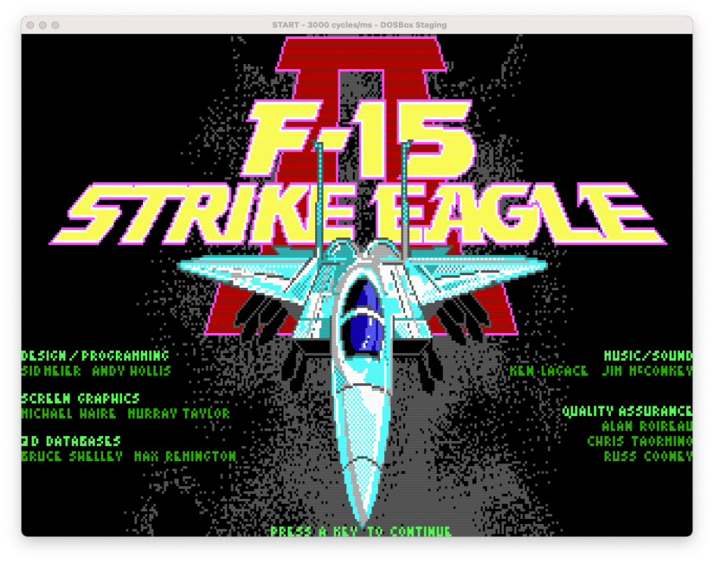
So I’ve been thinking about that data, and how it was out of range for a 16 colour image, and most notably how more often than not, both the high and low nibbles of the bytes shared the same value. This leads me to believe that perhaps the PIC file is packing two pixels into a single byte to squeeze out a little more compression. The way the values seem to flow in large runs seems to align with what we see for the image for the first line or so. Assuming a conventional left-right/top-down arrangement. (I managed to trick the game to show me the 320×200 title screen in 16 colours)
So it is quite possible that a 3rd level of compression here, in the form of packing, has been used with the 16 colour images. Furthermore, this appears to only be the case for the 320×200 16 colour images, which have the 0x0b format byte value. When I look at the ‘title640’ file (which has the 0xf5 format byte value), the values stay in the 0-15 range, at least for the top bit of the file. So perhaps the format byte is signalling this pixel packing? As only the 0x0b files are packed, while the 0xf5 files are not. Also interesting to note, is that the values for the format byte are actually twos-compliment of each other. (0x0b=11, 0xf5=-11). So maybe, just maybe, the positive/negative state of the value defines the pixel arrangement? Still not sure what to make of the magnitude, but we possibly have something here.
As I mentioned earlier, we’re going to render the image to a file, so basically we are just converting the PIC file into something we can open with a conventional image editor. So the first thing we need to do is decide on a format. At this stage, we want something that is really simple to code in without the use of an external library. So with that said, I’ve decided to go with PPM as the image format. Yes another vintage graphics file format. The reason being is that many tools can still read it (including the Preview app on my Mac, GIMP, and pretty much any Linux distro should be able to open it, as it is one of the core NetPBM formats) and it is blindingly simple to implement. The format consists of an ASCII based header, followed by ASCII or binary data. I’ll stick with binary as it is more compact. It also doesn’t need compression, which keeps things simple. The downside is that it does not support indexed colour, so we will have to render all our pixels into RGB triplets within the image data section. But I think that’s a positive for now. Once we have everything decoding correctly, I’ll likely swap out the PPM for something more modern, like PNG.
Since we suspect a pixel packing arrangement in some of the files we will need to have 2 different pixel rendering functions. One that writs out one pixel for every input byte, and another that outputs two. As for ordering of the pixels in the two pixel version, we’ll stick with the little-endian theme and have the low 4 bits represent the leftmost pixel. Although it looks like the format_identifier byte can be used as an indicator, we’ll specify it manually for now until we have investigated things further. As such, the format byte will be discarded here.
Next we need a palette to render with. So far all we have are colour indices into a palette, but we do not have the palette itself. Technically the CGA/EGA values are not indices as those adapters are RGBI (one bit for each colour component, and 1 bit of intensity), but they can still be handled as indices. VGA uses a DAC and a palette, so even in 16 colour mode the colours could be anything, however by default they are set to be compatible with CGA/EGA. As a result of the CGA/EGA hardwired colour coding, our palette for 16 colour mode is pretty straight forward. For the 256 colour files we can initially rely on the default mode 13h palette, which conveniently has the first 16 entries set to the CGA/VGA colours, so we only need one palette regardless of if it is a 16 colour or 256 colour image.
Writing the renderer
Let’s get to it. First thing I did was create a static palette of 256 entries containing the VGA Mode13 default palette, storing the entries in a simple RGB structure. The actual values I used I pulled from this repo.
#define PAL_MAX (0x3f)
typedef struct {
    uint8_t r;
    uint8_t g;
    uint8_t b;
} pal_entry_t;
The order of the component values is important, so we can simply write the entire entry to the output file, otherwise we would have to write one component at a time. PAL_MAX represents the maximum value any individual component can hold. This is needed for the PPM header, and since VGA has an 18 bit DAC, each component ranges from 0-63.
// write a pixel to the output stream, return 0 on success
int write_pixel(FILE *dst, uint8_t index, bool isPacked) {
    if(isPacked) {   // packed mode, write 2 pixels
        int nw = fwrite(&pal[index & 0x0f], 3, 1, dst); // write the first pixel
        index >>= 4; // shift in the next index
        nw += fwrite(&pal[index & 0x0f], 3, 1, dst); // write the second pixel
        return (nw != 2); // return 0 if we wrote 2 pixels
    }
    // normal unpacked mode
    return (1 != fwrite(&pal[index & 0x0f], 3, 1, dst));
}

int save_ppm(FILE *dst, FILE *src, uint width, uint height, bool isPacked) {
    // write the header for a binary PPM image file
    fprintf(dst, "P6\t%d\t%d\t%d\n", width, height, PAL_MAX);

    if(isPacked) {
        width /= 2; // adjsut the width for the fact that for every input byte, 2 pixels will be output
    }

    for(uint y = 0; y < height; y++) {
        for(uint x=0; x < width; x++) {

            uint8_t px = fgetc(src);
            if(feof(src)) { // we must be beyond the input data
                px = 0; // pad with 0 (black)
            }

            if(write_pixel(dst, px, isPacked)) {
                printf("Error: Unable to write to output\n");
                return -1;
            }
        }
    }
    return 0;
}
And that’s it, the pixel renderer and PPM file generation. save_ppm() is our main entry here, and it will iteratively call write_pixel() for each pixel position in the output. If packed it will call for every other position, as the write_pixel() routine will unpack, and output a pair of pixels.
With the last piece of the pipe in place there’s nothing left to do but to see what we get. First for our “normal” pixel arrangement:
RAW to PPM image converter
Resolution: 320 x 200
Opening RAW Image: 'TITLE16.RAW'	File Size: 72326
Warning: Source data exceeds image size, image will be truncated
Creating PPM Image: 'TITLE16.PPM'
Saving PPM Image
Image export completed without errors
And then for our packed pixel arrangement:
RAW to PPM image converter
Resolution: 320 x 200
Using Packed Pixel Arrangement
Opening RAW Image: 'TITLE16.RAW'	File Size: 72326
Warning: Source data exceeds image size, image will be truncated
Creating PPM Image: 'TITLE16.PPM'
Saving PPM Image
Image export completed without errors
Everything runs as I would expect. We talked about the size problem, so I’m ignoring that for now. So what does the output image look like? That, my dear reader, is the story for another post…
This Post is the fifth in a series of posts surrounding my reverse engineering efforts of the PIC file format that MicroProse used with their games. Specifically F-15 Strike Eagle II (Though I plan to trace the format through other titles to see if and how it changes). To read my other posts on this topic you can use this link to my archive page for the PIC File Format which will contain all my posts to date on the subject.

Leave a comment