In a previous post we investigated the remaining unknowns with the PIC90 PIC89 variant of the MicroProse PIC file format. This post will be more of the same, except this time we will tackle the PIC91 PIC90 variant, bringing us one step closer to fully understanding the format, and it’s evolution, based on the sample set of files we have available to us. Also as a side note before we go on here, in that previous post I’ve updated it a bit to include the CGA remap/dithering rendering at the end to be complete.
Just a reminder that from this post forward we will be using the new designations established for the variants in the previous two posts.
The PIC90 Format
I’ve kind of breezed over the arrangement of this format somewhat, mainly because it is already fairly well documented in the darklands.txt document. But we should recap things a bit before we go down the path of determining the purpose of the different blocks.
At its core the PIC90 consists of a series of blocks, there is no master header for the file. Each block is prefixed with a 2 character ASCII identifier for the block, The first character is always an uppercase letter, and the second is always a digit. After the identifier bytes is a 16 bit value representing the length of the block. With this little bit of information we can fully traverse any PIC90 file.
File: 'EARTHEGA.PIC'  [10371 bytes]
Offset    x0 x1 x2 x3 x4 x5 x6 x7 x8 x9 xA xB xC xD xE xF  Decoded Text
0000000x: 4D 30 02 03 00 FF 00 00 00 00 00 2A 00 2A 00 00  M 0 · · · · · · · · · * · * · ·
    ⋮
0000030x: 00 00 00 00 00 00 45 30 02 01 00 FF 00 11 22 33  · · · · · · E 0 · · · · · · " 3
    ⋮
0000040x: 00 00 00 00 00 00 00 00 00 00 00 00 43 30 02 01  · · · · · · · · · · · · C 0 · ·
    ⋮
0000051x: 00 00 58 31 6D 23 40 01 C8 00 0B 33 20 FD 0B 58  · · X 1 m # @ · · · · 3   · · X
    ⋮
0000288x: B5 28 06 [EOF]                                   · ( ·


     : Identifier
     : length
We can see in the excerpts from a file above showing each of the blocks for that file. And we can show that the 16 bit value that follows the block identifier is the length by checking against the position we see. The length does not include the block header with the the ID and length.
Block    Position in File    Length         Next Block
M0       0x00000000          0x0302 (770)   0x0004 + 0x0302 = 0x0306
E0       0x00000306          0x0102 (258)   0x030A + 0x0102 = 0x040C
C0       0x0000040C          0x0102 (258)   0x0410 + 0x0102 = 0x0512
X1       0x00000512          0x236D (9069)  0x0516 + 0x236D = 0x2883
[EOF]    0x00002883
Now that we can traverse the PIC90 file we can selectively look at blocks of interest to decode them. But first let’s wrap what we know into a simple structure.
typedef struct {
    char block_id[2];
    uint16_t len;     // length of the block, not incl this header
    uint8_t block[];  // the rest of the block
} pic90_block_t;
With the information we’ve covered here, and the structure above we can now write a simple program to open a PIC90 file, read a block header, print its ID and length, and then skip forward to the next block and repeat.
     0: Block: M0  Length: 770
   774: Block: E0  Length: 258
  1036: Block: C0  Length: 258
  1298: Block: X1  Length: 9069
 10371: EOF
We can take it a step further and have the program write each chunk out to its own file, for easier analysis, which I will use in the subsequent sections here for each block type. Interestingly, each of these files will still be a valid PIC file, in terms of structure. That’s all we need for now, we will elaborate on each type as we go through them below.
Based on the identifying program we wrote, I’ve cherry picked a couple of files from the available assets that cover off on everything we need to validate the PIC90 variant of the PIC file format here. We need to validate the following 5 things with this variant.
- The
M0block – documented to be the palette - The
X0block – documented to be image data (unpacked) - The
X1block – previously theorized to be a packed pixel encoded image data - The
E0block – previously theorized as a greyscale mapping - The
C0block – TBD
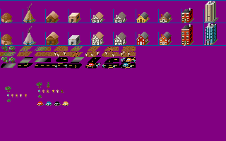
Analyzing: 'CIVILIZATION/CITYPIX1.PIC': PIC91: (PIC90)
	Unknown: 'E0' (Len: 258)
	Palette: Start: 0 End 255 (Len: 770)
	Image: 320x200 0x0b: max-bits: 11 (Len: 6803)
Analyzing: 'LIGHTSPEED/EARTHEGA.PIC': PIC91: (PIC90)
	Palette: Start: 0 End 255 (Len: 770)
	Unknown: 'E0' (Len: 258)
	Unknown: 'C0' (Len: 258)
	Image: 320x200 Packed 0x0b: max-bits: 11 (Len: 9069)
Let’s start with the image blocks first, as they will be key in validating the others.
PIC90 X0 Image Block
Lets start by taking a look at what a X0 block looks like. The first thing that we can see after the ID and length values is a pair of 16 bit values that are clearly the width and height of the image, exactly as we saw with PIC90 PIC89 after the type identifier word. What follows after that is the max bits value for the LZW compression, and this is the same as we’ve seen all along with PIC88. In theory we could strip off the first 8 bytes, and be left with a PIC88 file.
File: CITYPIX1.PX0  [6994 bytes]
Offset    x0 x1 x2 x3 x4 x5 x6 x7 x8 x9 xA xB xC xD xE xF  Decoded Text
0000000x: 58 30 4E 1B 40 01 C8 00 0B 87 20 FD 0B 18 04 80  X 0 N · @ · · · · ·   · · · · ·
0000001x: 40 83 2B E0 DD 33 F8 CF 20 8F 78 F1 E0 C9 C2 97  @ · + · · 3 · ·   · x · · · · ·
0000002x: 4F 96 C5 79 FC 18 1A AC 11 F1 9E 3C 7B F9 EC 89  O · · y · · · · · · · < { · · ·
0000003x: 9C 57 25 E3 41 48 34 E4 49 A4 28 4F DE 45 7E 25  · W % · A H 4 · I · ( O · E ~ %

58 30: Block identifier "X0"
4E 1B: Block Length 0x1B4E (6990)
40 01: Image Width 0x0140 (320)
C8 00: Image Height 0x00C8 (200)
0B: Max LZW Bits (11)
There is one thing we need to do first. The max bits value is just that, it is not a format identifier like it is with PIC88. It does not signal packed or unpacked here. So based on the description in the darklands document, the pixel data here is not packed, so we will need to negate this value if we were to strip off the rest of the header to write this out as a PIC88 format PIC file. So let’s do that and see what we get.

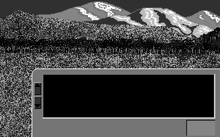
Indeed the data here is unpacked, or the image wouldn’t look correct, as we’ve seen before. Our colours are still off, but we haven’t decoded the palette yet. We will get to that later when we look at the M0 block.
typedef struct {
    uint16_t width;    // image width
    uint16_t height;   // image height
    uint8_t max_bits;  // max bits for LZW compression
    // data will be block length - 5 bytes long
    uint8_t lz_data[]; // variable length LZW data
} pic90_image_t;
PIC90 X1 Image Block
Next up is the X1 image block. We have hypothesized that this is the same form as X0, except the image data is in packed pixel form. In this case we don’t need to modify anything to the format byte, as it is already correct for signalling packed pixel data. So if we strip off the first 8 bytes, we should have a valid image.
File: EARTHEGA.PX1  [9073 bytes]
Offset    x0 x1 x2 x3 x4 x5 x6 x7 x8 x9 xA xB xC xD xE xF  Decoded Text
0000000x: 58 31 6D 23 40 01 C8 00 0B 33 20 FD 0B 58 68 CE  X 1 m # @ · · · · 3   · · X h ·
0000001x: 1D 48 06 02 5A 32 08 89 C0 BF 7F 7F 0E 12 B8 11  · H · · Z 2 · · · · · · · · · ·
0000002x: 50 D2 9D 43 88 EE DC 7B 78 E7 E1 BF 3B 20 29 42  P · · C · · · { x · · · ;   ) B
0000003x: 82 74 07 91 49 3C 1D 21 6E 7C 18 11 64 C0 46 06  · t · · I < · ! n | · · d · F ·

58 31: Block identifier "X1"
6D 23: Block Length 0x236D (9069)
40 01: Image Width 0x0140 (320)
C8 00: Image Height 0x00C8 (200)
0B: Max LZW Bits (11)
I think it’s safe to say our hypothesis was correct about the X1 image block, in that it is for packed pixel images. Now let’s see if we can fix the colours.
PIC90 M0 Palette Block
The M0 block is another one that we know about from the darklands document. Visually looking at the data and size it certainly fits the bill to be palette information. But let’s first look at its structure. First thing we note is that while 256 entries of palette data would take up 768 bytes, the structure has a size of 770. So there are 2 extra bytes, presumably header data. Looking at the first two bytes, we can see what looks like two 8 bit values, likely representing start and end indices for the palette, as described in the darklands document.
File: CITYPIX1.PM0  [774 bytes]
Offset    x0 x1 x2 x3 x4 x5 x6 x7 x8 x9 xA xB xC xD xE xF  Decoded Text
0000000x: 4D 30 02 03 00 FF 20 00 20 3F 15 3F 3F 15 3F 3F  M 0 · · · ·   ·   ? · ? ? · ? ?
0000001x: 15 3F 3F 15 3F 3F 15 3F 3F 15 3F 3F 15 3F 3F 15  · ? ? · ? ? · ? ? · ? ? · ? ? ·
0000002x: 3F 3F 15 3F 3F 15 3F 3F 15 3F 3F 15 3F 3F 15 3F  ? ? · ? ? · ? ? · ? ? · ? ? · ?
0000003x: 3F 15 3F 3F 15 3F 3F 15 3F 3F 15 3F 3F 15 3F 3F  ? · ? ? · ? ? · ? ? · ? ? · ? ?

4D 30: Block identifier "M0"
02 03: Block Length 0x0302 (770)
00: Start Index
FF: End Index
All that is left now is to extract the palettes we have and apply them to the image files we’ve already extracted. Again, for my code, I need to do a little conversion to put it into the PAL format that MicroProse seems to use, by stripping off all the header information, including the start and end indices. The end result is a file of 768 bytes of palette data.

The images look much better now. We can now properly decode a PIC90 image and render it as intended. So what do the remaining block types do?
typedef struct { // structure for a single palette entry
    uint8_t r;
    uint8_t g;
    uint8_t b;
} pal_t;

typedef struct {
    uint8_t first;  // first palette entry index
    uint8_t last;   // last palette entry index
    // data will be last-first+1 entries long
    pal_t p_data[]; // variable length RGB palette data
} pic90_palette_t;
PIC90 C0 Block
Now on to our first mystery block C0. This block seems to be formed similar to the palette block, except it has only one byte per entry, but also has the same 2 extra bytes to start off with.
File: EARTHEGA.PC0  [262 bytes]
Offset    x0 x1 x2 x3 x4 x5 x6 x7 x8 x9 xA xB xC xD xE xF  Decoded Text
0000000x: 43 30 02 01 00 FF 00 00 10 12 00 00 20 11 22 00  C 0 · · · · · · · · · ·   · " ·
0000001x: 33 11 00 00 00 33 00 00 00 00 00 00 00 00 00 00  3 · · · · 3 · · · · · · · · · ·
0000002x: 00 00 00 00 00 00 00 00 00 00 00 00 00 00 00 00  · · · · · · · · · · · · · · · ·
0000003x: 00 00 00 00 00 00 00 00 00 00 00 00 00 00 00 00  · · · · · · · · · · · · · · · ·

43 30: Block identifier "C0"
02 01: Block Length 0x0102 (258)
00: Start Index
FF: End Index
Does anyone see what I see here? If you recall in our examination of the PIC90 PIC89 format for Type F we found that the first 16 entries before the image data were likely CGA remap/dither data. This looks eerily similar, and I believe that C0 is a CGA colour mapping/dithering. Not sure why they have a full 256 entry table here, instead of just a 16 entry one? Perhaps that was a limitation of their MicroProse encoder, or just an oversight when converting the assets to PIC. (A full 256 colour palette was also included for this file, with only the first 16 entries having values)
Just to recap, the CGA map contains entries in the form of bytes, but the value in each byte is split into 2 nibbles, and each nibble only has the values from 0-3. Using a simple location based method, the lower or upper nibble is selected for which colour should be displayed for that pixel. Given that EARTHEGA is a 16 colour packed pixel image, only 16 entries are required for the table here. Only one way to find out, let’s apply it to the image and see what it looks like.

Not sure what CGA palette us supposed to be used here, but this one seemed the best. But most importantly, we see dithering happening in reasonable places, so I think the hypothesis is correct here that C0 is indeed CGA remap data.
typedef struct {
    uint8_t first;    // first map entry index
    uint8_t last;     // last map entry index
    // data will be last-first+1 entries long
    uint8_t m_data[]; // variable length entries
} pic90_map_t;
PIC90 E0 Block
Now on to our last mystery block E0. This block has the exact same form as C0. I had originally hypothesized that this was greyscale mapping data, and that made sense at the time for the file I was looking at with the data I was seeing, but I hadn’t considered another possibility. After looking at the data here, especially for EARTHEGA, and with what the C0 block seems to be fresh on my brain, I actually think this is a EGA mapping/dithering block now. In the same mode as the CGA map, where each nibble of data represents one of the 16 EGA colours to display, and which nibble to use is selected based on location on the screen, to create a simple dithering. What keyed me to this is the fact that most values in this block for the two files we are looking at are repeated values for both nibbles. However for CITYPIX1 which is a 256 colour image, the pattern occasionally breaks, using unique values for each nibble. While for EARTHEGA the values seem to simply reflect their index, so a straight pass-through. (it is a 16 colour image after-all)
File: EARTHEGA.PE0 [262 bytes]
Offset x0 x1 x2 x3 x4 x5 x6 x7 x8 x9 xA xB xC xD xE xF Decoded Text
0000000x: 45 30 02 01 00 FF 00 11 22 33 44 55 66 77 88 99 E 0 · · · · · · " 3 D U f w · ·
0000001x: AA BB CC DD EE FF 00 00 00 00 00 00 00 00 00 00 · · · · · · · · · · · · · · · ·
0000002x: 00 00 00 00 00 00 00 00 00 00 00 00 00 00 00 00 · · · · · · · · · · · · · · · ·
0000003x: 00 00 00 00 00 00 00 00 00 00 00 00 00 00 00 00 · · · · · · · · · · · · · · · ·
45 30: Block identifier "E0"
02 01: Block Length 0x0102 (258)
00: Start Index
FF: End Index
File: CITYPIX1.PE0 [262 bytes]
Offset x0 x1 x2 x3 x4 x5 x6 x7 x8 x9 xA xB xC xD xE xF Decoded Text
0000000x: 45 30 02 01 00 FF 00 11 22 33 44 55 66 77 88 99 E 0 · · · · · · " 3 D U f w · ·
0000001x: AA BB CC DD EE FF 00 00 00 00 00 00 00 00 00 00 · · · · · · · · · · · · · · · ·
0000002x: 00 00 00 00 00 00 00 00 00 00 00 00 00 00 00 00 · · · · · · · · · · · · · · · ·
0000003x: 00 00 00 00 00 00 00 00 00 00 00 00 00 00 00 00 · · · · · · · · · · · · · · · ·
⋮
000000Dx: 22 22 22 28 28 28 FB FB FB FB FB FB FB FB BB BB " " " ( ( ( · · · · · · · · · ·
000000Ex: BB BB BB BB BB BB CC CC CC CC CC CC CC CC 44 44 · · · · · · · · · · · · · · D D
000000Fx: 44 44 44 44 44 44 FF 7F 7F 7F 77 77 78 78 88 88 D D D D D D · · · · w w x x · ·
45 30: Block identifier "E0"
02 01: Block Length 0x0102 (258)
00: Start Index
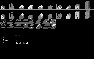
FF: End IndexNow before we get to the EGA mapping, I did also check to see if this was greyscale mapping. Doesn’t look quite right, too much detail is lost, especially in CITYPIX1.
Now let’s see how it looks with the EGA mapping.
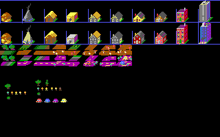

While EARTHEGA doesn’t do much to answer the question, CITYPIX1 certainly does. And with the confirmation here for EGA dithering, I think it affirms the CGA dithering as well. They are the same style blocks, we just didn’t have a good/obvious example here.
I think that wraps up our understanding of the PIC90 variant of the MicroProse PIC file format. At this point we know enough to decode, and re-encode the image assets for all the titles we have identified except for one. Next post I plan to begin to tackle the PIC93 variant.
This post is part of a series of posts surrounding my reverse engineering efforts of the PIC file format that MicroProse used with their games. Specifically F-15 Strike Eagle II (Though I plan to trace the format through other titles to see if and how it changes). To read my other posts on this topic you can use this link to my archive page for the PIC File Format which will contain all my posts to date on the subject.

Leave a comment